Design:
I owned an homebrew analog ATV receiver bought from PE1ACB for A while now and was very pleased with the good quality of the video signal. The only thing I didn’t like was the way you had to control the receiver with only the frequency setting on an LCD and A rotary encoder for adjusting. All other options where set with switches and an pot-meter.
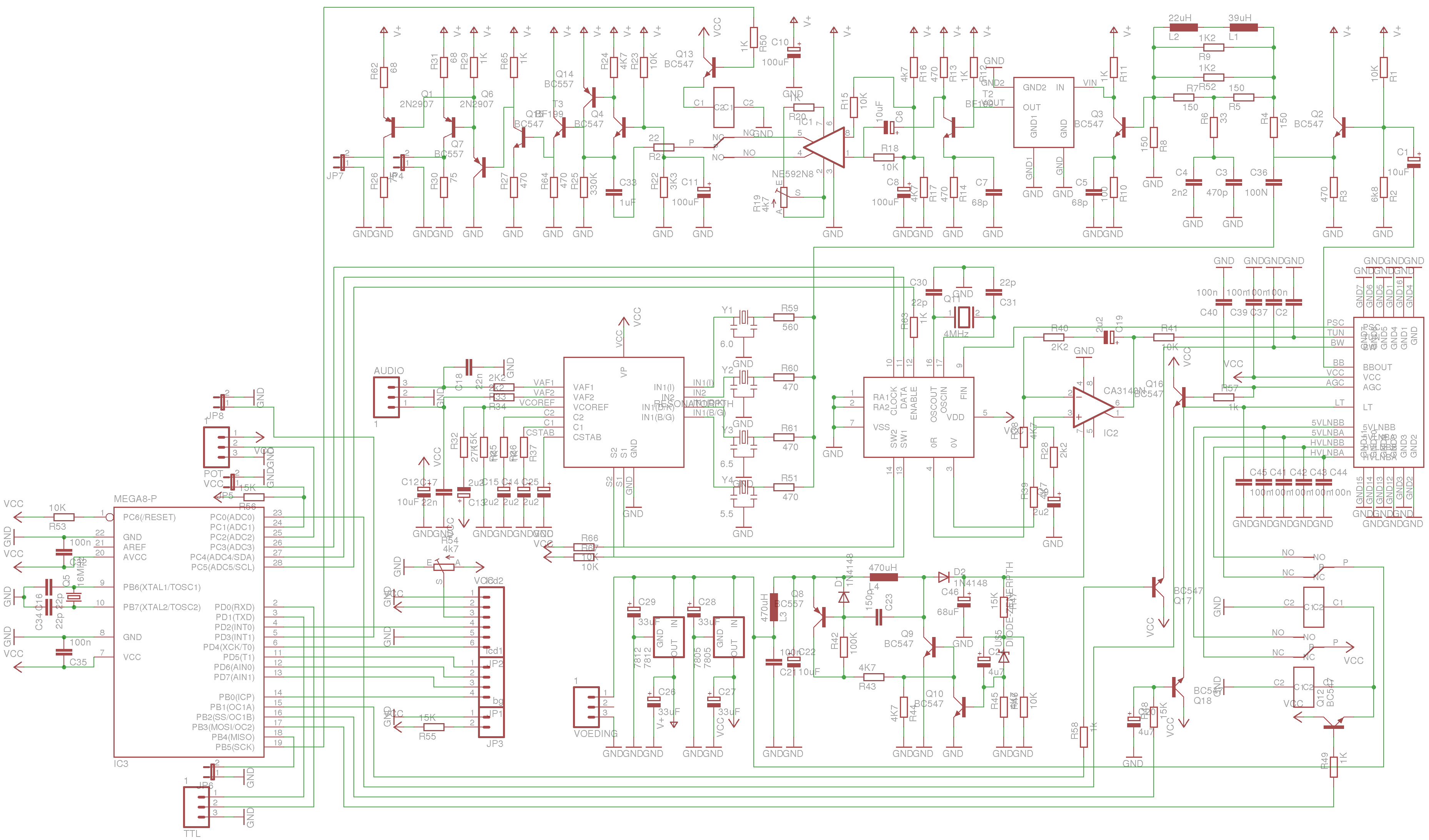
It took me some time to figure out how the pll (mc145155p2) had to be controlled but I managed to figure it out.
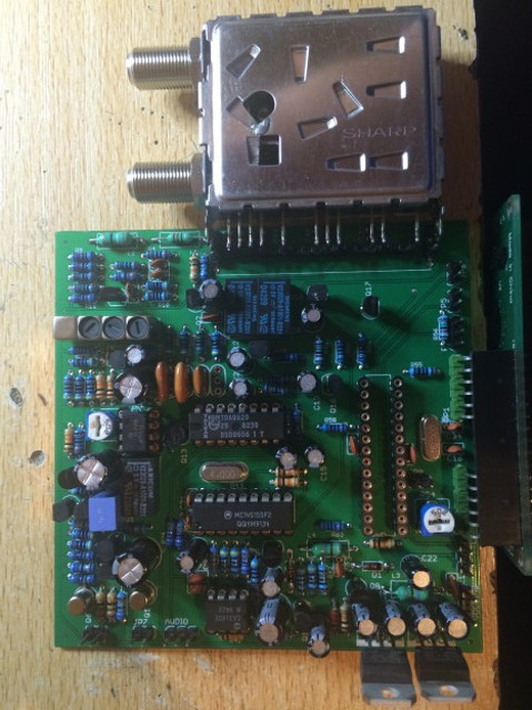
The receiver itself is build around the Sharp L77G05 tuner
Parts of the schematic and the explanation of how to control the tuner is available at the website of PE1CHY:
sharp schematic
explanation
The video and audio demodulation was also published by PE1CHY, if someone can deliver me the link I will post it here.
Once I got the pll software running on an arduino rom based atmel chip I was able to build more software options.
I also added the option to adjust the local oscillator setting so you can read out the frequency plus or minus the LO of the LNB or converter.
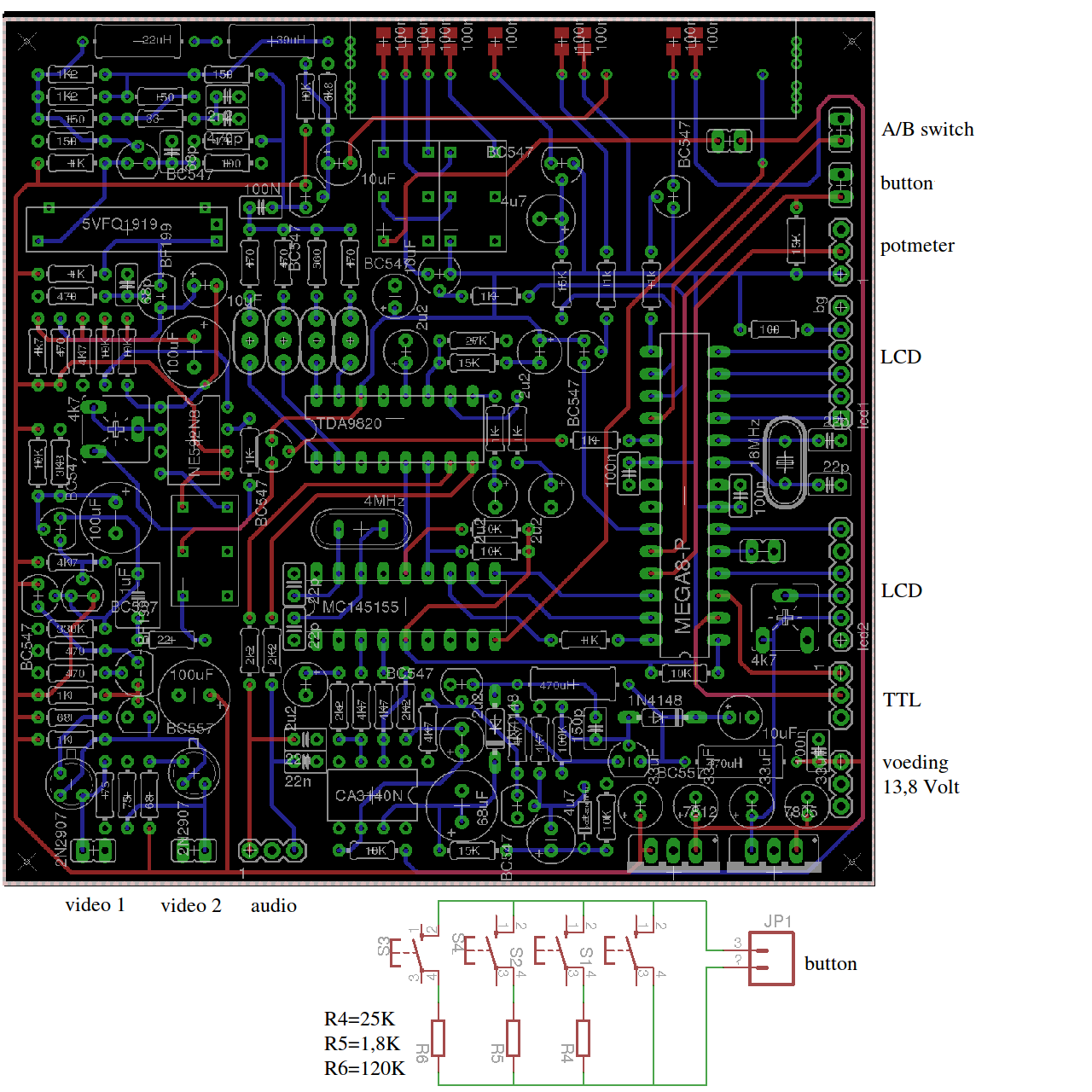
I had to design A new PCB for the extra hardware and the micro controller I wanted.
menu options:
Frequency adjust 950MHz to 2150MHz
audio carrier 5.5, 6.0 and 6.5 MHz (stereo in combination with 7.02 MHz).
Local oscillator -2147483648 MHz to 2147483647 MHz
Step size 1,10,50,100 MHz
Bandwidth 17 and 28 MHz
Low Threshold 0 to 31
there are 4 buttons connected to the board to adjust the parameters.
Parameter up
Adjust up
Adjust down
Back to frequency
Next to that there is also the possibility to connect A pot-meter to adjust the frequency from set frequency to 500 MHz up.
And an option for input A/B switch, I did this in the menu but I noticed it’s faster to have A switch for this function.
Al the above menu settings will be stored in EEprom separate for input A and input B.
This means you can use the receiver for 2 bands and just flip the switch to get from 3 cm to 13 cm.
Set input A for example for 10 GHz ( with LNB LO 9000 MHz):
LO 9000 MHz
video positive
audio 6,5 MHz
bandwidth 27 MHz
Set input B for example for 2330 MHz ( with chaparral 13cm converter LO 3800 MHz):
LO -3800 MHz
video negative
audio 6 MHz
Bandwidth 18 MHz
files:
schematic (png)
PCB Board (png)
PCB parts only (png)
eagle board file
Eagle schematic file
arduino ino file
Several builders have asked me for the type number of the relays I use: V23026-A1001-8202-5V
PE1ACB has his own receiver modified with the software I use on A separate control board, this design has exactly the same options:
PE1ACB design of this project
Copyrights:
All software is distributed under the GNU/GPL licence.
All hardware and designs are distributed under a Creative Commons license Attribution-ShareAlike 2.5.